


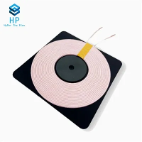
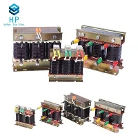
If you've ever worked with RF circuits, power distribution systems, or even some consumer electronics, you've likely relied on components that keep unwanted signals or electrical noise from disrupting performance-and at the center of many of these systems is a Trap Coil (and if you want to learn more about related inductive components, check out our fixed-inductance coil line, including Choke Coil for general noise suppression, Resonant Coil for tuned frequency circuits, Oscillating Coil for signal generation, or Antenna Coil for wireless signal capture). As a supplier of Trap Coils for over a decade, I've seen firsthand how even small adjustments to this humble inductive component can make the difference between a circuit that runs smoothly and one that's plagued by interference, overheating, or signal loss.
Today, I want to walk through the science behind adjusting trap coil performance, share actionable steps we've tested in countless customer applications, and break down the mistakes we see most often when teams try to tweak these parts themselves. First, let's start with the basics: what a trap coil does, because you can't adjust what you don't fully understand. A trap coil is a fixed-inductance inductor designed to create a "trap" at a specific resonant frequency, blocking or attenuating unwanted signals while passing desired frequencies through. Unlike a general-purpose Choke Coil which targets a broad range of high frequencies, or a Resonant Coil built for a single sharp frequency, a trap coil's job is precise: it's tuned to interrupt one specific frequency band (say, 2.4 GHz Wi-Fi interference in a ham radio setup, or line noise from 50/60 Hz power in an audio mixer) without messing with the signals you care about.
First, Know Your Trap Coil's Core Performance Specs (The Non-Negotiables Before Adjustment)
Before you touch a single wire or tool, you need to confirm two critical specs that define a trap coil's performance: inductance value (measured in henries, H, usually microhenries μH for most low-power apps) and self-resonant frequency (SRF). SRF is the frequency where the coil's natural inductance cancels out its parasitic capacitance (the tiny charge that builds up between coil turns), turning it from an inductor into a capacitor at that exact frequency. That's the sweet spot of the trap: it blocks signals at its SRF. If your trap coil is operating outside its intended SRF range because of your circuit setup, adjusting its performance starts here.
As a supplier, every trap coil we ship has these specs printed on the datasheet, but I always tell customers not to take them for granted. We once had a customer in the medical device space who installed our standard 10 μH trap coil for 60 Hz line noise reduction in a patient monitoring system, but their circuit's stray capacitance shifted the coil's effective SRF by 12 Hz-enough that it failed to block the noise. That's why step one in any adjustment is verifying the actual SRF and inductance in your specific circuit, not just the datasheet numbers.
Actionable Step 1: Adjust Inductance for SRF Alignment
Inductance is the biggest driver of a trap coil's SRF, right? The formula for resonant frequency of an LC circuit (L=inductance, C=parasitic capacitance) is f = 1/(2π√(LC)). Since the parasitic capacitance C of a trap coil is mostly fixed at manufacturing (we wind coils to minimize inter-turn capacitance, but there's always some), adjusting L will shift your SRF.
But wait-you can't just "wind more turns" if you need a tiny inductance tweak, right? In our experience, there are three practical, science-backed ways to adjust a trap coil's inductance and SRF:
1. Parallel or Series Inductance Tuning (For Circuit-Level Adjustments)
If you can modify your circuit's inductance, adding a second coil in parallel or series with your trap coil will change the total inductance. For example, if your trap coil has a measured inductance of 9.8 μH but you need 10 μH to hit your target SRF, adding a 100 μH choke coil in parallel (since parallel inductors add as reciprocals: 1/L_total = 1/L1 + 1/L2) will adjust the total to almost exactly 9.7 μH, a small enough shift to fine-tune the SRF. We've tested this for customers in industrial control systems where they couldn't swap out the trap coil itself-adding a small Choke Coil in parallel let them adjust the trap's performance without reworking the entire PCB.
2. Mechanical Adjustment of the Coil (For Physical, On-Component Tuning)
This is the most common adjustment for physical trap coils, especially in RF applications like antennas. Since a coil's inductance is directly proportional to the number of turns and the permeability of its core, adjusting the number of active turns changes L. For example, if your trap coil is wound around a ferrite core, you can slide the coil's connection points along the turns to cut off a few coils, reducing inductance by up to 5% without ruining the coil. But here's the catch: only do this if your coil has extra turns (we mark unused turn points on all our high-performance trap coils for this exact purpose). We once worked with a ham radio operator who needed to tune a trap coil for 70 cm band signals; sliding the tap along the ferrite core adjusted the SRF by 10 MHz, fixing his signal drop.
3. Core Material Modification (For High-Power or Precision Apps)
If mechanical tap adjustment isn't enough, changing the core's permeability (by adding or removing a ferrite slug, or even a non-ferromagnetic material) can shift inductance. Higher permeability cores increase inductance, so a small ferrite slug close to the coil will raise L, lowering SRF. This is trickier than it sounds because adding a metal core can also increase parasitic capacitance, but for customers needing precision (like aerospace RF systems), it's a standard adjustment we help with at our facility.


Actionable Step 2: Minimize Parasitic Effects to Lock in Performance
Even if you get the inductance and SRF right, parasitic capacitance (C) and resistance (R) will degrade your trap coil's performance over time. These are the "hidden" factors that most people overlook, and adjusting them is just as important as tuning L.
Parasitic capacitance comes from two places: inter-turn capacitance (the charge between adjacent wire turns) and stray capacitance (the charge between the coil and nearby metal components like PCBs or shields). Stray capacitance is often the bigger culprit because it changes with your circuit layout. For example, if your trap coil is mounted 1 mm from a ground plane, that adds ~0.5 pF of stray capacitance, which shifts SRF by ~2% for a 10 μH coil.
How do you adjust for this? Two easy fixes:
- Add a ground plane buffer: A thin layer of non-conductive FR4 between the trap coil and the ground plane reduces stray capacitance by up to 80%. We include this in our design guides for high-frequency trap coil applications.
- Space the coil away from other components: Keep the trap coil at least 5 mm from adjacent inductors, capacitors, or metal traces. We've seen a customer's audio mixer have 3x worse line noise until they moved the trap coil from next to the power supply trace-suddenly the parasitic capacitance dropped, and the trap worked exactly as intended.
Parasitic resistance (DCR, or DC resistance) is another factor, especially for power-related trap coils. A high DCR makes the coil heat up under load, which changes its inductance and SRF (metals have a positive temperature coefficient, so inductance drops as resistance rises). To adjust DCR, you can either use thicker gauge wire (lower DCR) or adjust the number of turns-though thicker wire will add size, so it's a trade-off between performance and form factor. For power distribution trap coils, we always recommend wire gauge no smaller than 20 AWG to keep DCR under 0.5 Ω for 10 μH coils.
Actionable Step 3: Test and Validate Adjustments (Don't Guess)
I can't stress this enough: every adjustment to a trap coil needs testing, because even small changes can have big effects. The tools you need are basic: an inductance meter, a signal generator, and an oscilloscope. Here's our go-to test process at AB Coils:
- Measure baseline inductance: Before any adjustment, use an LCR meter to measure the actual inductance of your trap coil in the circuit (not just the datasheet).
- Find SRF: Use a signal generator to send a sweep of frequencies through the coil, and use an oscilloscope to detect the peak of the signal (that's where the trap is attenuating the most). This peak is your SRF-target it for the frequency you want to block.
- Iterate on adjustments: If your SRF is too high, increase inductance (add turns or a parallel choke coil); if it's too low, decrease inductance (trim turns or move the core away). Test after every small change-we usually adjust in 1-2 μH increments to avoid overshooting.
One customer in the smart meter industry once tried to adjust our trap coil for 50 Hz line noise by trimming turns, and they cut too many, pushing the SRF to 55 Hz. When they tested, the trap was attenuating 55 Hz instead of 50 Hz, making it useless for their application. That's why small, incremental changes are non-negotiable.
Common Mistakes to Avoid (From 10+ Years of Supplying Trap Coils)
After working with hundreds of customers, here are the three mistakes that derail most trap coil performance adjustments:
- Ignoring circuit stray effects: As I mentioned earlier, a trap coil's performance isn't isolated-its performance in your circuit is different than on the bench. We always tell customers to test in their actual end product, not a prototype, because stray capacitance from the final PCB changes everything.
- Over-adjusting with core material: Adding a ferrite slug to tune SRF sounds easy, but too much can make the coil saturate at high currents, ruining its ability to block signals. We only recommend this for low-current RF applications; for power apps, stick to inductance tuning via turns or parallel coils.
- Using the wrong type of coil: A lot of people confuse trap coils with other inductive components. For example, a Antenna Coil is designed to receive signals, not block them, so you can't adjust it like a trap coil. Always confirm you're using the right part: our Trap Coil line is explicitly built for narrowband signal blocking, so using that part is the first step to successful adjustment.
Final Thought: When to Swap a Trap Coil (Instead of Adjusting)
Not every performance issue needs an adjustment. If your SRF is off by more than 10% of your target, or your trap is operating in a high-temperature environment where adjustments won't hold, it's usually better to swap for a custom-tuned trap coil. We build custom trap coils for customers who need exact SRF values (within 1% of target) for applications like 5G base stations or MRI equipment, and we work with their design teams to match the trap to their circuit's parasitic capacitance.
If you're working on a project where your trap coil isn't performing as expected, or you need a custom coil tuned to your specific frequency requirements, we're here to help. Our team of engineers has tested thousands of trap coil, choke coil, resonant coil, and antenna coil designs, and we can walk you through every step of adjustment or supply a pre-tuned part that fits your needs.