
Designing an oscillating coil - based filter is a crucial task in the field of electronics, especially for applications where frequency selection and signal filtering are required. As an Oscillating Coil supplier, I have extensive experience in this area and am eager to share some insights on how to design such a filter.
Understanding the Basics of Oscillating Coils
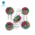
Before delving into the design of an oscillating coil - based filter, it is essential to understand what an oscillating coil is. An Oscillating Coil is a type of inductor that stores energy in a magnetic field when an electric current passes through it. It is a key component in many electronic circuits, including radio frequency (RF) circuits, where it can be used to create resonant circuits.
The basic principle behind an oscillating coil is based on Faraday's law of electromagnetic induction. When the current through the coil changes, it induces an electromotive force (EMF) in the coil, which opposes the change in current. This property allows the coil to store and release energy in the form of a magnetic field, creating an oscillating effect.
Key Parameters for Designing an Oscillating Coil - Based Filter
Inductance
Inductance is one of the most important parameters in the design of an oscillating coil - based filter. It is measured in henries (H) and determines the ability of the coil to store energy in the magnetic field. The inductance of a coil depends on several factors, including the number of turns, the cross - sectional area of the coil, and the permeability of the core material.
The formula for the inductance of a solenoid (a common type of coil) is given by:
[L=\frac{\mu N^{2}A}{l}]
where (L) is the inductance, (\mu) is the permeability of the core material, (N) is the number of turns, (A) is the cross - sectional area of the coil, and (l) is the length of the coil.
Resonance Frequency
The resonance frequency of an oscillating coil - based filter is another critical parameter. It is the frequency at which the inductive reactance ((X_{L}=2\pi fL)) and the capacitive reactance ((X_{C}=\frac{1}{2\pi fC})) in the circuit are equal. At the resonance frequency, the impedance of the circuit is at a minimum, and the circuit can efficiently pass signals at this frequency.
The formula for the resonance frequency ((f_{0})) of an LC circuit (a circuit consisting of an inductor (L) and a capacitor (C)) is:
[f_{0}=\frac{1}{2\pi\sqrt{LC}}]
Quality Factor (Q)
The quality factor (Q) of an oscillating coil - based filter is a measure of the efficiency of the coil. It is defined as the ratio of the energy stored in the coil to the energy dissipated per cycle. A high Q factor indicates that the coil has low losses and can store energy more efficiently.
The Q factor of a coil can be calculated using the formula:
[Q=\frac{X_{L}}{R}]
where (X_{L}) is the inductive reactance and (R) is the resistance of the coil.
Design Steps for an Oscillating Coil - Based Filter
Step 1: Determine the Filter Requirements
The first step in designing an oscillating coil - based filter is to determine the specific requirements of the filter. This includes the desired frequency range, the type of filter (e.g., low - pass, high - pass, band - pass, or band - stop), and the attenuation requirements.
For example, if you are designing a band - pass filter for a radio receiver, you need to determine the center frequency and the bandwidth of the filter. The center frequency is the frequency at which the filter has maximum transmission, and the bandwidth is the range of frequencies over which the filter allows signals to pass.
Step 2: Select the Coil and Capacitor Values
Based on the filter requirements, you need to select the appropriate values of the oscillating coil and the capacitor. The inductance of the coil and the capacitance of the capacitor determine the resonance frequency of the filter.
To calculate the required inductance and capacitance values, you can use the resonance frequency formula (f_{0}=\frac{1}{2\pi\sqrt{LC}}). Rearranging the formula to solve for (L) or (C), we get:
[L=\frac{1}{(2\pi f_{0})^{2}C}]
[C=\frac{1}{(2\pi f_{0})^{2}L}]
Step 3: Choose the Core Material
The core material of the oscillating coil can have a significant impact on its performance. Different core materials have different permeabilities, which affect the inductance of the coil.
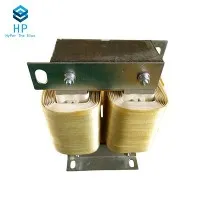
Common core materials include air, ferrite, and iron. Air - core coils have low inductance and are suitable for high - frequency applications. Ferrite - core coils have higher inductance and are often used in low - frequency applications. Iron - core coils have the highest inductance but also have higher losses.
Step 4: Design the Coil Structure
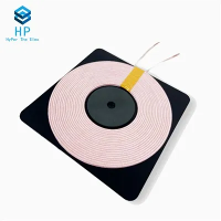
The structure of the coil, such as the number of turns, the winding type, and the coil diameter, also affects its performance. The number of turns determines the inductance of the coil, and the winding type can affect the self - capacitance and the Q factor of the coil.
For example, a single - layer solenoid coil has a lower self - capacitance compared to a multi - layer coil, which can improve the high - frequency performance of the coil.
Step 5: Test and Optimize the Filter
After designing the oscillating coil - based filter, it is necessary to test its performance. This can be done using a network analyzer or a spectrum analyzer. The test results can be used to optimize the filter design, such as adjusting the inductance, capacitance, or core material to meet the desired filter requirements.


Applications of Oscillating Coil - Based Filters
Oscillating coil - based filters have a wide range of applications in various electronic systems.
Radio Frequency (RF) Circuits
In RF circuits, oscillating coil - based filters are used for frequency selection and signal filtering. For example, in a radio receiver, a band - pass filter can be used to select the desired radio frequency signal and reject unwanted frequencies. Antenna Coils are often used in conjunction with oscillating coils to improve the performance of the RF circuit.
Power Supplies
In power supplies, oscillating coil - based filters can be used to reduce ripple and noise in the output voltage. A low - pass filter can be designed using an oscillating coil and a capacitor to smooth the DC output of the power supply.
Telecommunication Systems
In telecommunication systems, oscillating coil - based filters are used for channel selection and interference suppression. Trap Coils can be used to block specific frequencies and prevent interference from unwanted signals.
Contact for Procurement
If you are interested in purchasing high - quality oscillating coils for your filter design, we are here to help. Our company has a wide range of oscillating coils with different specifications to meet your specific needs. Whether you are working on a small - scale project or a large - scale industrial application, we can provide you with the right products. Please feel free to contact us to discuss your requirements and start the procurement process.
References
- "The Art of Electronics" by Paul Horowitz and Winfield Hill
- "RF Circuit Design" by Chris Bowick
- "Electronic Filter Design Handbook" by Don Lancaster