



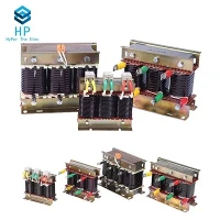
If you've ever worked with power systems, you've probably heard of current transformers (CTs) as the unsung workhorses of electrical infrastructure-those compact devices that keep meters running, relays tripping correctly, and maintenance teams from getting shocked. But for anyone who relies on CTs to monitor or protect their power networks, understanding their steady-state response isn't just a technical detail-it's the difference between reliable performance and costly errors. As a supplier of electronic current transformers (the kind that's become the go-to for modern grid applications), I've spent years walking engineers, electricians, and even small-business owners through this concept, so let's break it down clearly, no overly dense jargon, and with real-world context you can use.
First, let's define exactly what steady-state response means for an electronic CT. Put simply: when a current flows through the primary side of the CT at a constant, unchanging frequency (like the 50Hz or 60Hz standard that powers most of the world), the steady-state response is how the CT converts that primary current into a proportional, safe secondary current-without the fluctuations that happen during start-ups, short circuits, or other transient events. Transient response is for the short, chaotic bursts; steady-state is the everyday, consistent performance you can count on 99% of the time.
Now, why does this matter? Let's use a common example: a residential electric meter. When you charge your phone, run your dishwasher, or crank up your AC, you're drawing a steady current from the grid. That current flows through a conductor, and a CT installed near that conductor picks off a tiny portion to send to the meter. If the CT's steady-state response is off, the meter will undercount or overcount your energy use-and in some cases, that error could add up to hundreds of dollars a year, or even cause regulatory issues for utilities. That's why Transformer For Electric Meter is designed specifically to nail this steady-state performance, with tight accuracy tolerances tailored for the low, constant currents that residential and small-commercial meters handle.
Let's get into the nuts and bolts of how an electronic CT achieves this steady-state response, because it's different from traditional iron-core CTs you might be familiar with. Traditional CTs rely on magnetic induction: current in the primary coil creates a magnetic field in an iron core, which induces current in the secondary coil. But iron cores introduce things like hysteresis and saturation-minor delays or distortions that throw off steady-state accuracy, especially for low-level currents. Electronic CTs, by contrast, use solid-state sensors (like Rogowski coils or shunt resistors paired with signal conditioning circuits) that eliminate that iron-core magnetic interference. For steady-state, that means the secondary current is almost exactly proportional to the primary current, with error margins measured in fractions of a percent.
Wait, let's clarify that proportionality rule: for a CT, the current ratio is fixed. If you have a 1000:5 CT, that means for every 1000 amps flowing through the primary, you get 5 amps out the secondary-consistently, in steady state. But that ratio isn't perfect; errors come from two main sources in electronic CTs: magnitude error (the secondary current is a little more or less than 5 amps when primary is 1000) and phase error (the secondary current is slightly out of sync with the primary, which matters for power metering and relay protection). The steady-state response is all about minimizing these two errors during constant current flow.
For example, take Open End Current Transformers, a popular type for applications where you need to install CTs without disconnecting power lines (perfect for retrofitting existing buildings). Their steady-state response is calibrated for the exact current range of standard distribution circuits. Because they clamp around the conductor instead of being wired in series, their core is smaller and uses specialized signal conditioning to keep the secondary current proportional even at low steady-state loads-something that older open-core CTs struggled with, often drifting when current wasn't near their rated maximum. That's why when you're working on a retrofit, checking the steady-state response of your open-end CT is non-negotiable to avoid mismatches with your utility meter.
Another key factor for steady-state performance is frequency stability. Most grids run at a tight, consistent frequency (50Hz in Europe, most of Asia, Africa; 60Hz in North America), but some specialized grids (like those with renewable energy sources that vary slightly in frequency) need CTs that perform well across a range of steady frequencies. High-precision Current Transformers, designed for industrial power monitoring and advanced metering infrastructure (AMI), have signal conditioning circuits tuned to maintain accuracy across frequency variations. Their steady-state error is often less than 0.1%-a level you need if you're monitoring processes that rely on exact current measurements, like a manufacturing plant's production lines or a solar farm's output.
Let's talk about a specialized use case where steady-state response is critical: zero-sequence current detection. Zero-sequence current is the current that flows when there's a ground fault (like a line touching a tree or a wet ground), and it's steady when the fault is active (until the relay trips). Zero Sequence Current Transformers are built specifically to pick up these small steady-state ground currents, which are often just a few amps or less. Their steady-state response has to be sensitive enough to detect these tiny currents without picking up noise from other, larger steady currents in the system. If a zero-sequence CT's steady-state response was off by even a few tenths of an amp, a ground fault could go undetected, leading to equipment damage or even fire. That's why utilities rely on properly calibrated zero-sequence CTs for their protection schemes-their steady-state accuracy is what keeps the lights on and people safe.
You might be wondering: how do we test a CT's steady-state response? It's a standard procedure, but one that's easy to get wrong if you skip steps. The process involves applying a constant, known primary current (at the rated frequency) to the CT, then measuring the secondary current and phase difference over a set period (usually several minutes, to ensure no drift). For electronic CTs, you also test temperature stability-because as the CT warms up from use, its components can shift slightly, which would impact steady-state performance. That's a big difference from traditional CTs, which drift more with temperature, so electronic models are preferred for industrial applications where temperatures can fluctuate.


Wait, let's touch on a more advanced type of electronic CT that's become popular in recent years: Zero Magnetic Flux Current Transformers. These are used in very high-accuracy applications, like calibration labs or ultra-precise power metering, where even tiny steady-state errors are unacceptable. The zero magnetic flux design uses a feedback circuit to cancel out any residual magnetic field in the sensor, so the secondary current is a perfect, exact copy of the primary current in steady state. For context, a standard high-precision CT might have a steady-state error of 0.05%, but a zero magnetic flux CT can get down to 0.001%-the kind of accuracy you need when calibrating other CTs or measuring very small steady currents in R&D settings.
Now, let's address a common myth I hear all the time: some people think electronic CTs are all the same, and steady-state response is just a minor specification. That's not true. A CT that works fine for a single-family home might fail in a commercial building with non-linear loads (like LED lights or variable-speed motors) because while those loads aren't steady-state all the time, their average steady current is still what the CT has to measure. The quality of the signal conditioning, the type of sensor, and the calibration process directly impact steady-state performance. Cheap electronic CTs might cut corners on calibration, leading to drift over time-so when you're sourcing CTs, it's worth asking for their steady-state error specification, not just their current ratio.
As a supplier, I've seen firsthand what happens when you ignore steady-state response. A few years back, we worked with a small manufacturing plant that had installed a cheaper, uncalibrated CT for their main power meter. Within six months, their monthly energy bills were 12% higher than their usage projections. When we tested their old CT, we found its steady-state magnitude error was 11%-way above the acceptable 0.5% for commercial metering. We replaced it with a calibrated transformer for electric meter (linked here again for reference) with steady-state error under 0.2%, and their bills immediately matched their actual usage. That's the real-world impact of getting steady-state response right.
Another example: a solar farm in Arizona that was using a low-quality open-end CT for string current monitoring. Their steady-state response was off by 4% in the midday sun when currents were constant, leading them to underestimate their power output and lose out on $15,000 in incentive payments in one year. We swapped their CT for a better calibrated Open End Current Transformer, and their steady-state accuracy improved to 0.3%-they've since recovered over $20,000 in lost incentives, and their monitoring system now gives them reliable daily data.
So, to wrap this up: the steady-state response of an electronic current transformer is its ability to accurately convert a constant, steady primary current into a proportional secondary current, with minimal error in magnitude and phase, across a range of operating conditions. It's not just a technical spec-it's the backbone of reliable metering, protection, and monitoring for every electrical system, from a single home to a national power grid. The type of electronic CT you choose (whether it's a metering-specific model, an open-end retrofit CT, high-precision for industrial use, zero-sequence for ground faults, or zero magnetic flux for ultra-accuracy) directly impacts that steady-state performance, so never leave calibration and specification to chance.
If you're a utility engineer, a contractor working on a grid upgrade, a building owner updating your metering system, or anyone who relies on accurate current measurements, we can help you select the right electronic CT for your needs, test its steady-state performance to your requirements, and ensure it fits seamlessly into your system. We don't do one-size-fits-all solutions, because we know that steady-state response needs vary from application to application-whether you're monitoring 10 amps in a residential meter or 10,000 amps in a substation.