


Common mode chokes and differential mode inductors are both used in electromagnetic interference (EMI) filters, but they are designed to suppress different types of electrical noise.
A common mode choke mainly attenuates noise currents flowing in the same direction on multiple conductors. A differential mode inductor suppresses noise that appears between the conductors, with current flowing in opposite directions through the supply and return paths.
Choosing the wrong component can leave the dominant noise source untreated. It can also introduce unnecessary power loss, excessive voltage drop, or unexpected saturation problems.
For power supply designers and electronic equipment manufacturers, the important question is not simply which inductor has a higher inductance. It is whether the component provides the required impedance to the unwanted noise while allowing normal operating current to pass safely.
1. What Is the Difference Between Common Mode and Differential Mode Noise?
Before selecting an inductor, identify the type of conducted noise in the circuit.
Common mode noise (CM noise) appears on two or more conductors in the same direction relative to a common reference, such as protective earth or chassis ground. The unwanted current returns through parasitic capacitance, chassis connections, cables, or other unintended paths.
Common mode noise is often associated with fast switching transitions, high dv/dt nodes, parasitic capacitance, and unintended coupling between power circuits and the surrounding chassis.
Differential mode noise (DM noise) appears between two conductors. The noise current flows out through one conductor and returns through the other, forming a closed loop.
In switching power supplies, differential mode noise commonly comes from switching current pulses, rectifier commutation, input current ripple, and the interaction between switching devices and circuit inductance.
The distinction matters because the two noise modes require different filtering approaches.
A useful way to identify them is to measure both conductors with consistent current-probe directions:
If the noise currents flow in the same direction, the common mode component is dominant.
If they flow in opposite directions, the differential mode component is dominant.
In practice, both components may exist simultaneously. A power supply can have strong differential mode noise at one frequency and common mode noise at another.
2. How Does a Common Mode Choke Work?
A common mode choke normally consists of two or more windings on a shared magnetic core.
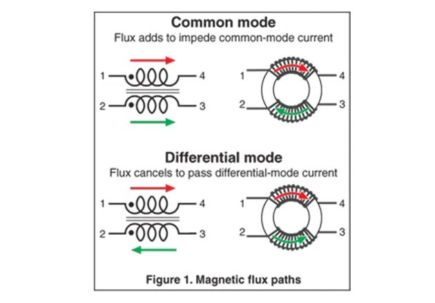
In a typical single-phase power input filter, the line and neutral conductors pass through separate windings. The windings are arranged so that normal differential load currents produce opposing magnetic fluxes inside the core.
Under normal operation, current flows toward the load through one winding and returns through the other. Their magnetic effects largely cancel, allowing the normal differential current to pass with relatively low magnetic impedance.
When common mode noise flows in the same direction through both windings, the magnetic fluxes reinforce each other. The choke then presents a much higher impedance to the unwanted common mode current.
This is the operating principle that makes a common mode choke useful in EMI suppression.
Why winding polarity matters
The two windings must have the correct relative polarity. If they are connected incorrectly, the normal load current may produce additive rather than cancelling flux.
This can cause excessive magnetizing current, core saturation, heating, or poor filter performance.
For custom common mode chokes, winding direction, terminal identification, and polarity should therefore be included in the electrical drawing or specification.
What happens to differential mode noise?
An ideal common mode choke has little impedance to differential mode current because the magnetic flux produced by the two windings cancels.
A real common mode choke, however, has leakage inductance. This leakage inductance can provide some differential mode impedance.
The amount depends on winding arrangement, spacing, coupling, and core construction. It should not be treated as a controlled differential mode inductance unless the manufacturer specifies and verifies it.
3. How Does a Differential Mode Inductor Work?
A differential mode inductor is generally placed in series with the power path. Unlike a common mode choke, it does not rely on two closely coupled windings to cancel the normal load-current flux.
In a single-phase input filter, a differential mode inductor may be placed in the line path, neutral path, or both paths, depending on the filter topology.
The inductor opposes changes in current according to its inductive impedance. When switching ripple or differential mode noise passes through it, the inductor restricts rapid current changes and works with the filter capacitors to attenuate unwanted frequency components.
For example, a series differential mode inductor combined with an X capacitor across line and neutral forms an LC low-pass filter.
The inductor stores magnetic energy during current changes and releases it as the current evolves. Its magnetic core must therefore withstand the actual current and flux conditions.
Unlike an ideal common mode choke carrying balanced differential load current, a differential mode inductor experiences the normal operating current as part of its magnetic excitation.
This makes saturation current, DC resistance, and thermal performance especially important.
4. Common Mode Choke vs Differential Mode Inductor: Main Differences
| Comparison | Common Mode Choke | Differential Mode Inductor |
|---|---|---|
| Main filtering target | Common mode noise | Differential mode noise |
| Typical winding structure | Two or more coupled windings on one core | Usually one winding per current path |
| Normal load-current flux | Designed to largely cancel | Produces magnetic flux in the core |
| Noise-current behavior | Same-direction currents reinforce flux | Opposite-direction currents create the filtering voltage |
| Main impedance characteristic | High common mode impedance | High differential mode impedance |
| Important magnetic parameter | Common mode impedance and leakage inductance | Inductance under operating current |
| Current rating considerations | Per-winding RMS current, thermal rise, imbalance | Continuous current, peak current, saturation current |
| Main loss considerations | Winding loss, core loss under common mode excitation | DCR loss, core loss, ripple-related loss |
| Typical filter partners | Y capacitors and other common mode filter elements | X capacitors and other differential mode filter elements |
| Common applications | AC input EMI filters, motor drives, communication lines | Switching power supply input filters, DC power filters |
The table describes typical implementations. Actual filter behavior depends on component construction, circuit topology, grounding, and parasitic elements.

5. Why Current Rating Is Different for These Two Components
Current rating is one of the most important differences when selecting a common mode choke and a differential mode inductor.
Common mode choke: normal current cancellation
In a properly balanced common mode choke, the normal differential load currents flow in opposite directions through the two windings.
Their magnetic flux largely cancels, so the core does not experience the same net magnetization that would occur if the full load current flowed through a single-winding inductor.
This allows a common mode choke to carry substantial normal load current without requiring a core sized as though the entire current were a DC magnetizing current.
However, this does not mean saturation is impossible.
Winding resistance and temperature rise still limit the continuous current rating. Current imbalance, unequal winding turns, asymmetrical connections, DC components, or common mode current can create residual core flux.
Therefore, when selecting a common mode choke, check:
Rated RMS current per winding
Maximum temperature rise
DCR of each winding
Common mode impedance across the target frequency range
Insulation voltage and winding-to-winding insulation
Permitted current imbalance, where specified
Do not assume that the common mode choke can carry unlimited DC current simply because its differential magnetic flux is designed to cancel.
Differential mode inductor: load current directly affects the core
A differential mode inductor normally carries the operating current in its magnetic path.
Its current produces magnetic flux, and the core must maintain sufficient inductance without entering an unacceptable saturation region.
When the current increases, the magnetic flux density also increases. If the core approaches saturation, inductance can fall sharply, reducing the intended filtering performance and potentially increasing current ripple.
For this reason, evaluate:
Rated continuous current
Saturation current
Peak operating current
Inductance at the specified DC bias
DCR and copper temperature rise
Core loss at the operating frequency and ripple level
A component's saturation current should not be confused with its thermal current rating. One describes magnetic behavior; the other describes the allowable heating under specified conditions.
A differential mode inductor may satisfy its saturation requirement but still overheat because of excessive copper loss.
6. How to Choose the Right Inductance and Impedance
A common mistake is to compare common mode chokes and differential mode inductors only by their inductance values.
The same nominal inductance does not mean the two components provide equivalent EMI filtering.
Selecting a common mode choke
For a common mode choke, start with the conducted EMI frequency range that needs attenuation.
Review the impedance or inductance characteristics over that range, not just the nominal inductance at one test frequency.
A practical selection should consider:
The frequency range of the measured common mode noise.
The required common mode impedance in that range.
Rated current and winding temperature rise.
Leakage inductance and its effect on differential mode behavior.
Parasitic winding capacitance and self-resonant frequency.
Insulation requirements between windings and terminals.
At higher frequencies, parasitic capacitance can bypass the inductive impedance. As a result, a choke with a high nominal inductance may not provide the expected attenuation across the entire EMI frequency range.
Selecting a differential mode inductor
For a differential mode inductor, the required inductance is determined by the filter design, the target ripple attenuation, and the interaction with the selected capacitor.
The component must maintain sufficient inductance under the actual DC operating current.
Check the inductance-versus-DC-bias curve if available. A nominal inductance measured at a small test signal may decrease significantly under full load.
Also compare DCR and AC winding losses. In a high-current input filter, excessive DCR can create unacceptable voltage drop and power dissipation.
The objective is to achieve the required differential mode attenuation without compromising current handling or thermal performance.
7. How Are They Used Together in an EMI Filter?
Many power supply EMI filters use both common mode and differential mode filtering because the noise source can produce both types of interference.
A typical single-phase AC input filter may include:
A common mode choke in the line and neutral paths.
An X capacitor connected between line and neutral.
Y capacitors connected from the appropriate conductors to protective earth or another permitted reference.
A differential mode inductor, where additional differential attenuation is required.
The common mode choke provides impedance to common mode noise. The X capacitor helps divert differential mode noise between the conductors, while a series differential mode inductor can increase the attenuation of the differential LC filter.
Y capacitors provide a return path for common mode noise, but their capacitance is constrained by leakage-current and safety requirements.
The exact topology depends on the power supply, grounding arrangement, applicable safety standards, and measured EMI results.
Adding more inductance is not always the solution. Filter stages can interact with the input impedance of the converter and create resonances. In some designs, damping or additional impedance control is needed to avoid unexpected peaks in the conducted emission spectrum.

8. What Should You Check When EMI Filtering Does Not Work?
If a product still fails conducted EMI testing after adding an inductor, first identify which noise mode remains excessive.
Do not replace the common mode choke with a larger differential mode inductor without confirming the noise path.
| Observed problem | Possible cause | What to investigate |
|---|---|---|
| Common mode emissions remain high | Insufficient common mode impedance | Review choke impedance across the failing frequency band |
| Differential mode emissions remain high | Insufficient series inductance or ineffective X-capacitor filter | Review DM filter response and capacitor placement |
| Choke becomes unusually hot | Excessive winding loss or unbalanced current | Check DCR, RMS current, winding balance, and core excitation |
| Differential mode attenuation is poor despite a common mode choke | Leakage inductance is too low | Add a properly designed DM filter stage if required |
| EMI peaks appear at unexpected frequencies | Filter resonance or parasitic coupling | Review component parasitics, layout, and damping |
| Common mode choke loses performance at high frequency | Parasitic capacitance or self-resonance | Check impedance curves and winding construction |
| Results change significantly with cable position | Common mode current paths and cable coupling | Review chassis bonding, cable routing, and grounding |
For conducted EMI troubleshooting, measure common mode and differential mode components separately where possible. This helps determine whether the problem is in the filter component, the PCB layout, the switching node, or the external cable and chassis arrangement.
9. What Information Should You Provide When Ordering a Custom Choke or Inductor?
A custom magnetic component should be specified according to its actual filtering function.
For a common mode choke, provide:
Number of conductors and windings
Rated RMS current per winding
Target common mode impedance or inductance
Frequency range requiring attenuation
Maximum DCR per winding
Insulation and dielectric withstand requirements
Maximum dimensions and mounting method
Operating temperature and cooling conditions
For a differential mode inductor, provide:
Required inductance
Operating DC current
Peak current and ripple current
Required inductance retention under DC bias
Maximum DCR
Operating frequency range
Core temperature or temperature-rise limit
Mounting and mechanical restrictions
If the final inductance or impedance target has not been determined, provide the circuit schematic, input voltage, switching frequency, load current, and EMI test results.
The manufacturer can then evaluate the magnetic structure and propose a suitable design.
For both component types, define the measurement conditions for inductance, impedance, and DCR. A nominal value without a test frequency, signal level, or DC-bias condition may lead to inconsistent comparisons between suppliers.

10. Frequently Asked Questions
Q1: Can a common mode choke replace a differential mode inductor?
Not as a direct replacement. A common mode choke is designed to provide high impedance to common mode noise while allowing balanced differential current to pass with relatively low impedance. Its leakage inductance may provide some differential mode filtering, but it should not be treated as a dedicated differential mode inductor without verified performance data.
Q2: Can a differential mode inductor suppress common mode noise?
A conventional single-winding differential mode inductor is not designed to provide the same common mode impedance as a coupled common mode choke. Its effectiveness depends on the current paths and grounding arrangement, so it should not be used as a substitute for a properly designed common mode filter.
Q3: Why does a common mode choke have two windings?
The two windings allow normal differential load currents to produce opposing magnetic flux, while common mode noise currents produce reinforcing flux. This provides selective impedance to common mode interference.
Q4: Does a common mode choke need a high saturation current rating?
Its normal differential load current is designed to produce largely cancelling flux, so the core does not experience the same magnetizing effect as a single-winding inductor carrying that current. However, current imbalance, DC components, and common mode excitation can still produce net flux. Thermal current rating and magnetic operating limits must both be checked.
Q5: What is the purpose of leakage inductance in a common mode choke?
Leakage inductance represents the portion of magnetic flux that does not couple both windings equally. It can provide some differential mode impedance, but its value depends on winding geometry and construction. It should be measured if it is important to the filter design.
Q6: Should common mode and differential mode noise be filtered separately?
They should at least be identified separately during EMI analysis. A combined EMI filter may suppress both modes, but the component values and filter topology must be selected according to the measured noise spectrum and circuit conditions.
Conclusion
Common mode chokes and differential mode inductors serve different purposes in EMI filter design.
A common mode choke uses coupled windings to cancel the magnetic effects of normal differential load current while presenting high impedance to common mode noise. A differential mode inductor is placed in the power path and directly opposes changes in differential current.
For common mode choke selection, prioritize common mode impedance, winding current rating, insulation, leakage inductance, and high-frequency parasitics. For differential mode inductor selection, focus on inductance under DC bias, saturation current, DCR, ripple current, and thermal performance.
When both types of conducted noise are present, using the two components together in a properly designed EMI filter is often more effective than trying to solve every EMI problem with a single inductor.