


When selecting an inductor for a switching power supply, engineers usually check inductance, rated current, DCR, and component size. However, one specification that should never be overlooked is saturation current, also known as Isat.
Saturation current describes the current level at which an inductor begins to lose a specified amount of its inductance. If the current becomes too high, the magnetic core can no longer maintain its normal operating behavior.
This can lead to increased current ripple, higher peak current, additional power losses, and unstable operation in a power supply.
However, saturation current is not the same as the maximum continuous current an inductor can carry. An inductor may reach magnetic saturation before its winding becomes too hot. In other cases, it may exceed its thermal limit while still maintaining sufficient inductance.
Understanding this difference is essential when selecting power inductors for DC-DC converters, AC-DC power supplies, LED drivers, battery-powered equipment, and industrial electronics.
1. What Is Saturation Current in an Inductor?
Saturation current is the current at which an inductor's inductance decreases by a specified percentage from its initial value.
An inductor stores energy in a magnetic field. When current flows through its winding, it generates a magnetic field inside the core. As the current increases, the magnetic flux density inside the core also increases.
At relatively low current levels, the magnetic core operates in a region where its permeability remains reasonably stable. The inductance changes very little.
As the current continues to increase, the magnetic material approaches saturation. Its effective permeability begins to decrease, and the inductance falls.
This is the reason engineers need to check saturation current when selecting a power inductor.
For example, a manufacturer may define the saturation current as the current at which the initial inductance has decreased by 20 percent.
This does not mean the inductor suddenly stops working at that current. It means its magnetic performance has changed by the manufacturer's specified amount.
Different manufacturers may use different definitions, so the test conditions must always be checked.
2. How Does Magnetic Core Saturation Happen?
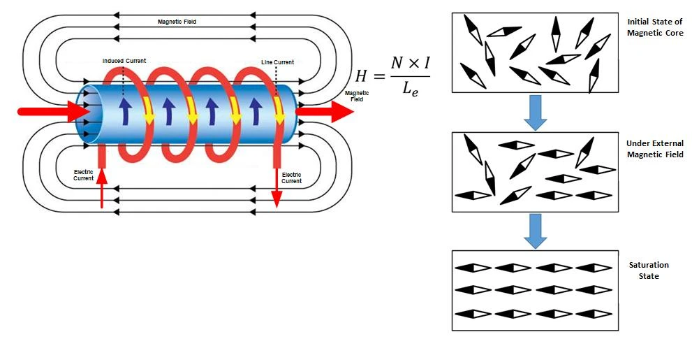
The magnetic core inside an inductor carries the magnetic flux generated by the winding current.
As current increases, magnetic field strength increases. The core initially responds by carrying more magnetic flux.
However, magnetic materials have a finite ability to increase their flux density. As the material approaches its saturation region, further increases in magnetic field strength produce progressively smaller increases in flux density.
The effective permeability decreases, and the inductance becomes lower.
This behavior is particularly important in switching power supplies because the inductor normally carries both DC current and switching ripple current.
The DC component creates a steady magnetic bias. The ripple current increases and decreases around this operating point during each switching cycle.
If the combined current becomes too high, the core may enter its saturation region.
For this reason, average current alone is not sufficient when selecting an inductor. The maximum instantaneous current must also be considered.
3. What Happens When an Inductor Reaches Saturation?
When an inductor approaches magnetic saturation, its inductance decreases. The effect on the circuit depends on the converter topology, operating conditions, and degree of inductance loss.
Several problems may occur in a switching power supply.
Increased current ripple
Inductance determines how quickly current changes in response to an applied voltage.
When inductance decreases, the current can rise and fall more quickly during each switching cycle.
This increases current ripple and may affect output voltage stability.
Higher peak current
A reduction in inductance allows current to increase more rapidly during the switching interval.
The peak current may become higher than expected, placing additional stress on the MOSFET, diode, rectifier, and other power components.
Increased power losses
Higher current can increase winding losses and semiconductor conduction losses.
The magnetic core may also experience additional losses depending on its material, operating frequency, and magnetic flux waveform.
If the inductor operates too close to its saturation limit, its temperature may rise significantly.
Power supply instability
In some converter designs, a large reduction in inductance changes the current ramp and the converter's operating behavior.
The controller may reach its current limit earlier than expected. Output regulation may deteriorate, and protection circuits may activate.
In severe cases, repeated overcurrent events can damage the power stage.
Saturation does not automatically cause immediate component failure. However, it can remove the operating margin required for stable power conversion.
4. What Is the Difference Between Saturation Current and Rated Current?
Saturation current and RMS current describe different operating limitations.
This distinction is important because an inductor may meet one current rating but fail the other.
| Parameter | Meaning | Main concern |
|---|---|---|
| Saturation current | Current at which inductance decreases by a specified percentage | Magnetic performance |
| RMS current | Current associated with a specified winding temperature rise | Thermal performance |
| Rated current | Manufacturer-defined operating current based on specified conditions | Overall operating limit |
| DCR | DC resistance of the winding | Voltage drop and copper loss |
Saturation current is a magnetic limit
Saturation current indicates how the magnetic core responds when current increases.
It helps engineers determine whether the inductor can maintain sufficient inductance under the expected operating current.
RMS current is a thermal limit
RMS current is mainly related to the heat generated by current flowing through the winding resistance.
Manufacturers commonly specify RMS current based on a particular temperature rise above ambient temperature.
For example, one datasheet may specify a current rating at a 20 degree Celsius temperature rise, while another may use a 40 degree Celsius temperature rise.
These ratings should not be compared directly without checking the test conditions.
Why both ratings matter
Consider two possible situations.
An inductor may have sufficient thermal capacity but reach magnetic saturation during peak current.
Another inductor may maintain its inductance under peak current but become too hot during continuous operation.
Both components may be unsuitable for the application.
A reliable design must satisfy both magnetic and thermal requirements.
5. Why Do Different Manufacturers Specify Different Saturation Currents?
Two inductors with similar dimensions and nominal inductance may have different published saturation current ratings.
One reason is that manufacturers do not always use the same percentage of inductance reduction to define Isat.
Common definitions include:
10 percent inductance reduction
20 percent inductance reduction
30 percent inductance reduction
50 percent inductance reduction in some product ranges
A higher percentage reduction can produce a higher published saturation current, even when the component does not necessarily provide better performance in the intended circuit.
Consider an inductor with an initial inductance of 10 uH.
| Inductance reduction | Inductance at the specified point |
|---|---|
| 10 percent | 9 uH |
| 20 percent | 8 uH |
| 30 percent | 7 uH |
| 50 percent | 5 uH |
If one manufacturer defines Isat at a 10 percent reduction and another defines it at a 30 percent reduction, their published current ratings are not directly comparable.
When comparing components, check the saturation definition and review the complete inductance versus DC bias curve whenever possible.
6. How Does Core Material Affect Saturation Current?
The magnetic core material has a direct influence on how an inductor responds to increasing current.
Different materials have different permeability, saturation characteristics, core losses, and temperature behavior.
Ferrite cores
Ferrite is widely used in high-frequency power inductors because suitable ferrite grades can provide relatively low core losses.
However, some gapped ferrite designs exhibit a relatively sharp reduction in inductance as current approaches saturation.
The designer therefore needs to maintain sufficient peak current margin rather than operating close to the saturation point.
Powder cores
Powder cores contain distributed air gaps within the magnetic structure.
This can produce a more gradual reduction in inductance as current increases. Their soft saturation behavior can be useful in applications with substantial DC bias or current transients.
However, powder cores are not automatically better for every application. Core loss, operating frequency, temperature, size, and cost must also be considered.
Comparing ferrite and powder cores
| Selection factor | Ferrite | Powder core |
|---|---|---|
| Saturation behavior | Can show a relatively sharp inductance drop | Often shows more gradual inductance reduction |
| Core loss | Low loss is possible with suitable grades | Depends strongly on material and frequency |
| DC bias performance | Depends on gap design and core material | Often useful for applications with significant DC bias |
| Thermal performance | Depends on material, flux density, and frequency | Depends on material, flux density, and frequency |
| Design consideration | Maintain sufficient margin before saturation | Check inductance reduction and core loss under actual conditions |
The correct material should be selected according to the application's current waveform and loss requirements, not simply by choosing the material with the highest saturation flux density.


7. How to Select an Inductor Based on Saturation Current
A practical selection process starts with the actual current flowing through the inductor.
Step 1: Determine the maximum peak current
Identify the highest instantaneous current expected during normal operation and relevant transient conditions.
In a switching converter, peak current includes the DC component and switching ripple.
Also consider:
- Maximum load
- Minimum and maximum input voltage
- Start-up behavior
- Load transients
- Current limit operation
- Overload and short circuit conditions
For example, a converter may have a normal output current of 3 A, but its inductor peak current may be 3.6 A because of switching ripple.
Selecting an inductor based only on the 3 A output current could result in insufficient saturation margin.
Step 2: Check the manufacturer's Isat definition
Find out how the supplier defines saturation current.
A value based on a 10 percent inductance reduction is not equivalent to a value based on a 30 percent reduction.
If the datasheet provides an inductance versus DC current curve, use it to determine the actual inductance at the expected peak current.
Step 3: Check inductance under DC bias
Nominal inductance is usually measured under specified small-signal conditions.
However, a power inductor operates with current flowing through its winding.
Check whether the inductance remains high enough under the expected DC bias.
This is particularly important for buck converters, boost converters, and other circuits where current ripple depends directly on inductance.
Step 4: Verify the RMS current rating
After checking magnetic performance, confirm that the inductor can carry the required RMS current without exceeding its temperature limit.
A higher saturation current does not automatically mean a higher thermal current rating.
Step 5: Evaluate temperature and operating conditions
Core saturation characteristics can change with temperature.
Check the manufacturer's curves or test data at relevant temperatures rather than assuming that the room temperature Isat value applies under every operating condition.
Also consider PCB copper area, airflow, nearby heat sources, and enclosure temperature.
Step 6: Verify performance in the actual circuit
Test the inductor under the real operating waveform.
Measure current ripple, peak current, temperature rise, and output behavior at the relevant input voltage and load conditions.
A datasheet rating is a starting point. The finished circuit determines whether the component is suitable.
8. How to Read an Inductance Versus DC Bias Curve
An inductance versus DC current curve is one of the most useful tools for evaluating saturation performance.
The horizontal axis represents DC bias current. The vertical axis represents the measured inductance.
At low current, inductance generally remains close to its initial value. As current increases, the curve begins to fall.
The shape of the curve tells the engineer how the inductor behaves under increasing magnetic bias.
There are two common patterns.
Sharp saturation: Inductance remains relatively stable and then drops rapidly near the saturation point. The design should maintain adequate distance from this region.
Soft saturation: Inductance decreases gradually as current increases. This behavior can provide more predictable performance during current transients, although the actual inductance must still remain within the application's acceptable range.
When reviewing a curve, check:
The initial inductance and its tolerance.
The current at which the inductance begins to decrease.
The inductance value at the expected peak current.
The temperature at which the curve was measured.
The test frequency and measurement conditions.
Do not judge an inductor only by the current value printed on the first page of its datasheet.

9. What Happens If the Saturation Current Is Too Low?
Choosing an inductor with insufficient saturation current can create problems that are sometimes mistaken for controller or circuit design faults.
| Observed problem | Possible saturation-related cause | What to check |
|---|---|---|
| Output voltage ripple increases | Inductance falls under peak current | Inductance under DC bias |
| MOSFET current rises unexpectedly | Reduced inductance allows faster current increase | Switching current waveform |
| Power supply enters current limit | Inductor reaches its magnetic limit | Peak current and controller current limit |
| Inductor temperature increases | Higher current and magnetic losses | RMS current, DCR, and core loss |
| Converter becomes unstable | Inductance changes beyond the design range | Operating inductance and converter stability |
| Performance deteriorates at high load | Current approaches the saturation region | Full load current waveform |
Not every symptom indicates magnetic saturation. Similar problems can result from excessive DCR, poor PCB layout, inadequate cooling, incorrect compensation, or unsuitable switching components.
The current waveform and inductance under bias should be measured before replacing the inductor.
10. How to Test Inductor Saturation Current
For engineers evaluating a new inductor or verifying a supplier's specifications, saturation performance should be checked under controlled measurement conditions.
A typical test process includes the following steps.
Step 1: Measure initial inductance
Measure the inductance without DC bias using an LCR meter or suitable impedance analyzer.
Record the measurement frequency, AC test level, and ambient temperature.
Step 2: Apply DC bias current
Use a DC bias source or a suitable test fixture to increase the current through the inductor in controlled steps.
The measurement equipment must be capable of measuring inductance while DC bias is applied.
Step 3: Record inductance at each current level
Measure and record the inductance as the bias current increases.
Compare each value with the initial zero bias inductance.
Step 4: Identify the specified inductance reduction
Determine the current at which inductance has decreased by the percentage specified by the manufacturer.
For example, if the agreed definition is a 20 percent reduction, identify the current at which the measured inductance reaches 80 percent of its initial value.
Step 5: Repeat at relevant temperatures
If the component will operate over a wide temperature range, repeat the measurement under representative temperature conditions.
This is important because the magnetic properties of the core can change with temperature.
Step 6: Compare the result with the application requirement
The measured saturation behavior should be checked against the actual peak current and the minimum inductance required by the circuit.
A component that meets its published Isat definition may still be unsuitable if its inductance has already fallen too far at the application's normal operating current.
11. What Should You Specify When Ordering a Custom Inductor?
When requesting a custom power inductor, providing only the nominal inductance and saturation current is not enough.
The manufacturer needs to understand the operating conditions and the required magnetic performance.
| Specification | Information to provide |
|---|---|
| Inductance | Nominal value and tolerance |
| Saturation current | Required current and acceptable inductance reduction |
| Peak current | Maximum instantaneous operating current |
| RMS current | Continuous or waveform based current requirement |
| Operating frequency | Switching frequency and relevant frequency range |
| DCR | Maximum acceptable winding resistance |
| Core material | Preferred material, if already defined |
| Temperature | Ambient temperature and maximum permitted temperature rise |
| Dimensions | Maximum length, width, and height |
| Mounting | SMD, through hole, or custom mounting structure |
| Application | DC-DC converter, LED driver, power supply, automotive electronics, or other use |
| Testing | Inductance, DC bias, DCR, temperature rise, and other acceptance requirements |
For a switching power supply, providing the current waveform or at least the peak and RMS current values is particularly useful.
If the design has a strict minimum inductance requirement under DC bias, specify that requirement directly instead of relying only on a nominal saturation current.
This allows the manufacturer to evaluate the core material, magnetic structure, winding arrangement, and component dimensions against the actual application.
12. Frequently Asked Questions
Is saturation current the maximum current an inductor can carry?
No. Saturation current describes the current at which inductance drops by a specified amount. It is a magnetic performance limit, not necessarily the maximum safe continuous operating current.
The thermal current rating must also be checked.
What is a good saturation current for an inductor?
There is no universal value. The required saturation current depends on the application's maximum peak current, acceptable inductance reduction, converter topology, and operating temperature.
Is a higher saturation current always better?
Not necessarily. A higher Isat may result from a larger core, different core material, different winding design, or a more relaxed inductance reduction definition.
Compare the inductance versus current curves and other electrical parameters rather than relying on Isat alone.
Can an inductor operate above its saturation current?
It depends on the application and how saturation current is defined. Some inductors exhibit soft saturation and can continue operating with reduced inductance.
However, operating above the specified saturation point may cause excessive ripple, current stress, or instability. It should not be treated as an acceptable operating condition without circuit level verification.
Why is saturation current different from RMS current?
Saturation current relates to magnetic flux and inductance reduction. RMS current relates mainly to winding heating.
An inductor may reach its saturation limit before reaching its thermal limit, or the reverse may happen.
Does core material affect saturation current?
Yes. Core material, air gap structure, magnetic path, and core geometry all affect how inductance changes under current bias.
Ferrite and powder cores can exhibit different saturation characteristics, so the actual inductance curve should be reviewed.
How can I reduce the risk of inductor saturation?
Select an inductor with sufficient peak current capability, check inductance under DC bias, maintain appropriate current margin, and verify the design under maximum load and transient conditions.
A larger or differently structured core may also be necessary if the existing component cannot maintain the required inductance.
Conclusion
Saturation current is an important parameter because it indicates how an inductor's magnetic performance changes as current increases.
When the magnetic core approaches saturation, inductance decreases. This can increase current ripple, raise peak current, affect converter stability, and place additional stress on other power components.
However, Isat should never be evaluated in isolation. Engineers also need to consider RMS current, DCR, core loss, temperature rise, and the actual current waveform.
For reliable inductor selection, compare the manufacturer's saturation definition, review the inductance versus DC current curve, and verify the component under real operating conditions.
When a standard inductor cannot meet the required peak current or inductance stability, a custom magnetic design may provide a more suitable solution.