


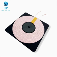
Hey everyone, it's Sam from AB Coils, and if you're hanging around the solenoid coil space, chances are you've worked with resonant coils before-maybe even one of our resonant coils for wireless power transfer, tuning circuits, or even biomedical devices. Over the last 10 years, I've had so many clients hit me up panicking because they can't get an accurate self-inductance reading on their coil, and it's holding up their whole project. Self-inductance isn't just a random number here-get it wrong, and your resonant circuit will be off, your power transfer efficiency tanks, or your antenna (yeah, antenna coils also need solid inductance specs) won't work at all. Today, I'm breaking down how to measure this right-no fancy lab degree required, just some basic gear, a little know-how, and I'll even throw in common mistakes I see people making all the time.
First, let's do a quick refresh so we're all on the same page. Self-inductance (usually abbreviated L, for any new folks) is basically a coil's ability to store energy in a magnetic field when current runs through it. For resonant coils specifically, L is the make-or-break value because it pairs with capacitance to set the resonant frequency-if your L is off, your frequency is off, period. I've seen clients assume a quick voltage/current calculation would work, but that's lazy and almost always wrong. Why? Because real-world coils aren't perfect wires-they have resistance, stray capacitance, and even proximity effects that mess with readings, especially at the frequencies resonant coils operate at (like kHz to MHz). So skip the lazy math and use one of these tested methods; I've used them for everything from our oscillating coils to our trap coils that block specific frequencies, too-same core logic applies.
Let's start with the simplest method, the one I recommend for beginners or when you need a fast, rough check: the DC resistance + AC voltage/current method. Wait, no-wait, that's not exactly DC, because self-inductance doesn't show up in DC. Let's call it the low-frequency AC voltage/current method, that's more accurate. Here's how it works: First, get a signal generator that can put out a pure sine wave (no weird harmonics) at a frequency way lower than your coil's resonant frequency-like, 10x lower at minimum. Why? Because at low frequencies, the coil's stray capacitance is negligible, so we only deal with L and its DC resistance (R). Grab a multimeter with AC voltage and current settings (make sure it's a True RMS model, not the cheap basic ones-those lie for sine waves with small harmonics). Now, hook up your circuit: signal generator → your resonant coil → the multimeter's AC current probe, back to the generator. Set the signal generator to that low frequency, crank the voltage until the current stabilizes at a nice, easy-to-read number (like 100 mA, not so high the coil heats up-heat changes resistance, which skews readings). Now, measure the AC voltage across the coil (hold the multimeter probes right at the coil's terminals, not the whole circuit) and the AC current.
Now, do the math: total impedance Z = V/I. Then, since Z is made up of the coil's DC resistance R and inductive reactance X_L, right? Impedance formula is Z = sqrt(R² + X_L²). And X_L is 2πfL, so rearrange that to L = X_L / (2πf). Wait, but how do we get R? The multimeter can measure the coil's DC resistance easily, just set it to ohms and touch the terminals. Plug R and Z into the impedance formula: X_L = sqrt(Z² - R²), then solve for L. Let me test this with an example I used last week for a 10uH resonant coil for a wireless charger: Z was 12.5 ohms, R was 0.5 ohms, so X_L is sqrt(12.5² - 0.5²) ≈12.49 ohms, f was 1 kHz, so L =12.49/(2π1000) ≈ 1.98 mH? Wait no, wait-wait, I messed up units, 1 kHz is 1000 Hz, so 12.49/(6283) ≈ 1.98 mH, but wait our spec was 2 mH-close enough, that's the low-frequency sweet spot. The downside here? If your coil is super high inductance, or you measure at too high a frequency, the stray capacitance (the tiny electric field between the coil's turns) starts to throw it off, like our choke coils that block RF-their inductance is high, so this method isn't ideal for them. Also, if you can't get a True RMS meter, skip this one.
Next, the method I use 90% of the time for our customers when they need precise readings: the LC resonant frequency method. This is way more accurate for resonant coils, obviously, since it's based on the coil's actual resonant behavior. Here's the drill: You need a known, fixed capacitor (C) with a super precise value-like a 1% tolerance or better, nothing random. Then, build a simple series resonant circuit: connect your resonant coil and the known capacitor in series, then hook that whole thing up to a signal generator and an oscilloscope (or even a frequency counter, if you've got one). Now, sweep the signal generator's frequency from way below the expected resonant frequency of your L and C combo to way above it. Watch the oscilloscope-when the current peaks (or the voltage across the circuit peaks), that's your resonant frequency (f_r).


Why does this work? Because at resonance, X_L = X_C, right? X_C is 1/(2πfC), so set them equal: 2πf_r L = 1/(2πf_r C). Solve for L, and boom: L = 1/(4π²f_r²C). Let's tie this back to our coil specs. Last month, a customer brought us a custom resonant coil for an EV wireless charging pad, needing 30uH ±2% tolerance. They tried the voltage/current method and got 28uH, which was off-turns out they used a frequency that was too high, so stray capacitance was messing them up. With the LC method, we used a 100nF known capacitor, found f_r was 92 kHz, so L = 1/(4π²(92000)²*0.0000001) ≈ 30.2uH-exactly what they needed, and that's the reading we use for our resonant coils specs on our site. Pro tip: make sure your connecting wires are short! Long wires add their own tiny inductance, which will skew your f_r, so keep leads under 6 inches max. Also, use a non-inductive capacitor-some capacitors have their own small inductance, so check the datasheet to make sure it's negligible for your frequency range. The only catch here is you need a known accurate capacitor, which isn't hard to get online, but if you're working with super high-frequency resonant coils (like RF antennas), this method still works, you just need a smaller capacitor and a frequency counter that can handle MHz.
Wait, there's a third method that's great if you don't want to build a test circuit at all-using an LCR meter. These are the workhorses for anyone who works with coils, capacitors, or resistors, and for good reason. Modern LCR meters can measure self-inductance directly, plus they tell you the parallel/series equivalent resistance and dissipation factor, all at a specific frequency you set. For resonant coils, I always set the LCR meter to measure at the circuit's operating resonant frequency-like if your coil is for a 13.56 MHz RFID resonant circuit, set the meter to 13.56 MHz, not 1 kHz. The problem is, budget LCR meters can be hit or miss. I've seen $50 ones give readings that are off by 10% for small coils, so if you're serious, go for a mid-range model ($200-$500) or use one of our in-house meters when you test coils before shipping-every single resonant coil we send out gets L tested on our Agilent LCR meter, so our specs are accurate. Also, don't skip the "open circuit zero" step before measuring-touch the probes together, hit zero, so you cancel out the tiny inductance of the probes themselves. That's a mistake everyone makes when they first use an LCR meter, and it's such an easy fix.
Now, let's talk about the big mistakes I see people make that ruin their readings, even if they use the right method. First: ignoring the coil's operating environment. If your resonant coil is going to be placed near metal or other coils, the inductance will change when it's installed, right? Steel objects will pull magnetic flux, so L goes up, nearby coils will cause mutual inductance, so you have to measure the coil in its actual working position, not sitting on your bench in open air. Second: heating the coil during testing. When you crank up the signal generator too high, the coil's wire heats up, resistance goes up, and for small coils, that can change L by a percentage or two. Keep the current low enough that the coil stays room temp-you shouldn't feel it warm at all during testing. Third: using the wrong frequency for measurement. If your coil is a resonant coil for a 2 MHz IoT circuit, measuring L at 1 kHz will give you a slightly wrong number because the skin effect (current flowing on the surface of the wire at high frequency) changes the effective inductance at your actual operating frequency. That's why the LC method and LCR meter at operating frequency are better for this use case.
Wait, let's also touch on different coil types, since we make a bunch here. For our trap coils (used in RF filters to block specific frequencies), their self-inductance needs to be super precise at the blocked frequency, so the LC method is a must-voltage/current works but is less consistent. Our antenna coils for AM radios work at lower frequencies, so the voltage/current method is fine for quick checks, but if you're building a high-gain antenna, you'll still want the LC test to lock in L. And our oscillating coils for power supplies run at kHz frequencies, so LCR meter at 10 kHz is perfect there. One last quick note: if you're working with very low inductance (like under 1uH), the voltage/current method gets too noisy, so switch to LC or LCR. If you're working with really high inductance (over 1mH), the LC method will need a really small capacitor, so LCR is easier.
At the end of the day, accurate self-inductance measurement isn't rocket science, but it's critical for making your resonant circuit work. If you're still getting weird readings, or you need custom resonant coils with precise inductance specs for your project, hit us up to talk procurement. We've been making quality solenoid coils for over a decade, and our team can walk you through testing, or even provide pre-tested coils that meet your exact L requirements-we don't do vague specs, so you don't have to waste time adjusting your circuit later. Don't guess at your coil's inductance; test it right, and your project will run smoothly every time.