


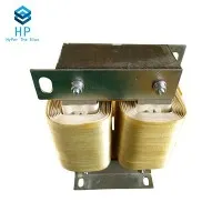

In the realm of electrical engineering, resonant coils play a pivotal role in various applications, from radio frequency (RF) circuits to wireless power transfer systems. As a dedicated resonant coil supplier, I understand the importance of accurately measuring the quality factor (Q factor) of these coils. The Q factor is a critical parameter that characterizes the performance of a resonant coil, reflecting its efficiency and selectivity. In this blog post, I will delve into the intricacies of measuring the Q factor of a resonant coil, sharing insights and practical methods based on my experience in the industry.
Understanding the Quality Factor
Before we explore the measurement techniques, let's first understand what the Q factor represents. The Q factor of a resonant coil is defined as the ratio of the energy stored in the coil's magnetic field to the energy dissipated per cycle. Mathematically, it can be expressed as:
[ Q = 2\pi \frac{\text{Energy stored}}{\text{Energy dissipated per cycle}} ]
A high Q factor indicates that the coil has low losses and can store energy efficiently, resulting in a sharp resonance peak. Conversely, a low Q factor implies higher losses and a broader resonance curve. In practical applications, a high Q factor is often desirable as it enhances the performance of resonant circuits, such as improving the sensitivity of RF receivers and increasing the efficiency of wireless power transfer systems.
Factors Affecting the Q Factor
Several factors can influence the Q factor of a resonant coil, including:


- Conductor Resistance: The resistance of the coil's conductor contributes to energy dissipation in the form of heat. Lower conductor resistance leads to a higher Q factor.
- Skin Effect: At high frequencies, the skin effect causes the current to concentrate near the surface of the conductor, increasing the effective resistance and reducing the Q factor.
- Dielectric Losses: If the coil is wound on a dielectric core or surrounded by a dielectric material, dielectric losses can occur, further reducing the Q factor.
- Magnetic Core Losses: In coils with magnetic cores, hysteresis and eddy current losses in the core can also contribute to energy dissipation and lower the Q factor.
Measuring the Q Factor
There are several methods available for measuring the Q factor of a resonant coil. Here, I will discuss three commonly used techniques: the voltage - standing - wave ratio (VSWR) method, the bandwidth method, and the Q - meter method.
VSWR Method
The VSWR method is based on the principle of measuring the reflection coefficient of a resonant circuit. When a resonant coil is connected to a transmission line, the reflection coefficient at resonance can be related to the Q factor.
- Set up the test circuit: Connect the resonant coil to a transmission line with a known characteristic impedance (Z_0). Use a network analyzer to measure the reflection coefficient (\Gamma) of the circuit as a function of frequency.
- Find the resonance frequency (f_0): Locate the frequency at which the reflection coefficient is minimum. This frequency corresponds to the resonance frequency of the coil.
- Calculate the Q factor: The Q factor can be calculated using the following formula:
[ Q=\frac{f_0}{\Delta f} ]
where (\Delta f) is the bandwidth of the resonance curve, defined as the frequency difference between the two points where the reflection coefficient is (\frac{1}{\sqrt{2}}) times its minimum value.
Bandwidth Method
The bandwidth method is a simple and straightforward way to measure the Q factor. It relies on the relationship between the resonance frequency, the bandwidth, and the Q factor of a resonant circuit.
- Apply a sinusoidal signal: Connect the resonant coil to a signal generator and a spectrum analyzer. Apply a sinusoidal signal with a variable frequency to the coil.
- Measure the resonance frequency (f_0) and the bandwidth (\Delta f): Adjust the frequency of the signal until the output voltage across the coil reaches its maximum value. This frequency is the resonance frequency (f_0). Then, measure the frequency difference between the two points where the output voltage drops to (\frac{1}{\sqrt{2}}) times its maximum value. This frequency difference is the bandwidth (\Delta f).
- Calculate the Q factor: Use the formula (Q = \frac{f_0}{\Delta f}) to calculate the Q factor of the coil.
Q - Meter Method
A Q - meter is a specialized instrument designed specifically for measuring the Q factor of resonant circuits. It works by applying a known voltage to the resonant coil and measuring the voltage across a capacitor in the circuit.
- Connect the coil to the Q - meter: Follow the manufacturer's instructions to connect the resonant coil to the Q - meter. Make sure the coil is properly tuned to resonance.
- Measure the Q factor: The Q - meter will directly display the Q factor of the coil. Some Q - meters also allow you to measure other parameters, such as the inductance and capacitance of the circuit.
Practical Considerations
When measuring the Q factor of a resonant coil, it is important to consider the following practical aspects:
- Test Environment: The test environment can have a significant impact on the measurement results. Make sure to perform the measurements in a shielded enclosure to minimize the effects of electromagnetic interference.
- Coil Orientation and Placement: The orientation and placement of the coil can affect its performance and the measurement results. Keep the coil away from other conductive objects and magnetic materials during the measurement.
- Frequency Range: Different measurement methods may be more suitable for different frequency ranges. Choose the appropriate method based on the operating frequency of the coil.
Applications of Resonant Coils
Resonant coils find wide applications in various fields, including:
- Radio Frequency (RF) Circuits: In RF receivers and transmitters, resonant coils are used to tune the circuits to specific frequencies, improving the selectivity and sensitivity of the systems. You can find more information about Oscillating Coil and Antenna Coil on our website.
- Wireless Power Transfer (WPT) Systems: Resonant coils are essential components in WPT systems, enabling efficient transfer of power over a distance. Our Resonant Coil products are designed to meet the high - performance requirements of WPT applications.
- Medical Devices: In medical imaging and therapy equipment, resonant coils are used to generate and detect magnetic fields, facilitating accurate diagnosis and treatment.
Conclusion
Accurately measuring the Q factor of a resonant coil is crucial for ensuring its optimal performance in various applications. By understanding the factors affecting the Q factor and using the appropriate measurement techniques, engineers and designers can select the right resonant coil for their specific needs. As a resonant coil supplier, I am committed to providing high - quality products with precise Q factor specifications. If you are interested in our resonant coil products or have any questions about Q factor measurement, please feel free to contact us for procurement and further discussions.
References
- Hayt, W. H., & Kemmerly, J. E. (2001). Engineering Circuit Analysis. McGraw - Hill.
- Pozar, D. M. (2011). Microwave Engineering. Wiley.
- Ramo, S., Whinnery, J. R., & Van Duzer, T. (1994). Fields and Waves in Communication Electronics. Wiley.