


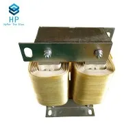

Hey there! As a filter inductor supplier, I've had my fair share of discussions about these nifty components. One question that often pops up is, "What is the equivalent circuit of a filter inductor?" Well, let's dive right in and break it down.
First off, let's understand what a filter inductor does. In simple terms, a filter inductor is used to filter out unwanted frequencies from an electrical signal. It's like a bouncer at a club, only letting in the "good" frequencies and keeping the "bad" ones out. This is crucial in many electronic applications, from power supplies to audio systems.
Now, onto the equivalent circuit. An ideal filter inductor can be represented as a pure inductance (L). But in the real world, things aren't that simple. A real - world filter inductor has some additional elements in its equivalent circuit.
The most basic equivalent circuit of a filter inductor includes an ideal inductor (L), a series resistance (Rs), and a parallel capacitance (Cp). The series resistance (Rs) accounts for the resistance of the wire used to wind the inductor. Every wire has some resistance, and this resistance can cause power losses in the form of heat. So, it's important to consider this when designing a circuit with a filter inductor.
The parallel capacitance (Cp) is due to the capacitance between the turns of the inductor. When you wind a wire into a coil, there's a small amount of capacitance between adjacent turns. This capacitance can have an impact on the inductor's performance, especially at high frequencies.
Let's talk a bit more about how these elements interact. The series resistance (Rs) affects the quality factor (Q) of the inductor. The quality factor is a measure of how "good" an inductor is. A higher Q value means less power loss and better performance. The formula for the quality factor is Q = ωL/Rs, where ω is the angular frequency. So, as the resistance (Rs) increases, the quality factor decreases.
The parallel capacitance (Cp) forms a resonant circuit with the inductor. At the resonant frequency, the impedance of the equivalent circuit reaches a maximum or minimum value, depending on the circuit configuration. This resonant frequency can cause problems in some applications, as it can lead to unwanted oscillations or signal distortion.
Now, let's take a look at different types of filter inductors and how their equivalent circuits might vary.
BUCK Inductor
A BUCK Inductor is commonly used in buck converters, which are a type of DC - DC converter that steps down the voltage. In a buck converter, the inductor stores energy when the switch is closed and releases it when the switch is open. The equivalent circuit of a buck inductor is similar to the general filter inductor equivalent circuit, but the values of the components might be different. For example, since buck inductors often handle relatively high currents, the series resistance (Rs) needs to be as low as possible to minimize power losses.
Coil Inductor
Coil Inductors come in various shapes and sizes. They can be air - core or have a magnetic core. The type of core used can significantly affect the equivalent circuit. For example, an inductor with a magnetic core will have a higher inductance value compared to an air - core inductor of the same size. Also, the magnetic core can introduce additional losses, which are represented by an equivalent resistance in the equivalent circuit.
Toroidal Inductors
Toroidal Inductors are known for their high inductance and low electromagnetic interference (EMI). The toroidal shape helps to contain the magnetic field within the inductor, reducing EMI. In terms of the equivalent circuit, toroidal inductors usually have a relatively low parallel capacitance (Cp) because of their compact and symmetric design. This makes them suitable for high - frequency applications.
So, why is understanding the equivalent circuit of a filter inductor so important? Well, it helps in circuit design. By knowing the equivalent circuit, engineers can accurately predict how the inductor will perform in a circuit. They can calculate the power losses, the resonant frequency, and the impedance at different frequencies. This information is crucial for optimizing the performance of the overall circuit.
As a filter inductor supplier, I know that different applications require different types of inductors. Whether you're working on a small - scale audio project or a large - scale power system, choosing the right filter inductor is essential. And understanding the equivalent circuit is the first step in making that choice.


If you're in the market for filter inductors, I'd love to help you find the perfect fit for your project. Whether you need a specific type of inductor or have questions about the equivalent circuit, I'm here to assist. Just reach out, and we can start a discussion about your requirements.
In conclusion, the equivalent circuit of a filter inductor is a combination of an ideal inductor, a series resistance, and a parallel capacitance. Different types of filter inductors, like buck inductors, coil inductors, and toroidal inductors, have variations in their equivalent circuits based on their design and application. Understanding these equivalent circuits is key to successful circuit design.
References
- Grover, F. W. (1946). Inductance Calculations: Working Formulas and Tables. Dover Publications.
- Terman, F. E. (1955). Electronic and Radio Engineering. McGraw - Hill.