

Hey there! As a supplier of Coil Inductors, I often get asked about the principle behind these nifty little components. So, let's dive right in and break it down in a way that's easy to understand.
First off, what the heck is a Coil Inductor? Well, a Coil Inductor, as the name suggests, is basically a coil of wire. You can check out more about it Coil Inductor. It's one of the fundamental passive electronic components, and it plays a crucial role in all sorts of electronic circuits.


The principle of a Coil Inductor is rooted in electromagnetism. When an electric current flows through a wire, it creates a magnetic field around that wire. Now, when you coil that wire up, things get even more interesting. The magnetic fields of each turn of the coil add up, creating a stronger and more concentrated magnetic field inside the coil.
Let's talk about how this magnetic field thing works. According to Faraday's law of electromagnetic induction, a changing magnetic field can induce an electromotive force (EMF) in a conductor. In the case of a Coil Inductor, when the current flowing through the coil changes, the magnetic field around the coil also changes. And this changing magnetic field then induces an EMF in the coil itself.
This induced EMF has a very important property. It always opposes the change in current that caused it. This is known as Lenz's law. So, if the current through the coil is increasing, the induced EMF will act to try and reduce the current. And if the current is decreasing, the induced EMF will try to keep the current flowing.
This opposition to the change in current is what gives Coil Inductors their unique behavior in circuits. They act like a sort of "electrical inertia." Just like a heavy object in motion resists changes in its velocity, a Coil Inductor resists changes in the current flowing through it.
One of the key parameters of a Coil Inductor is its inductance, which is measured in henries (H). Inductance is a measure of how much induced EMF the inductor will generate for a given rate of change of current. The inductance of a coil depends on several factors, such as the number of turns in the coil, the cross - sectional area of the coil, the length of the coil, and the permeability of the core material (if there's a core inside the coil).
If you increase the number of turns in the coil, the inductance goes up. That's because more turns mean a stronger magnetic field and more induced EMF for a given change in current. Similarly, increasing the cross - sectional area of the coil also increases the inductance. A larger area allows for a greater magnetic flux, which in turn leads to more induced EMF.
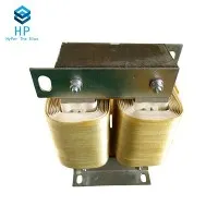
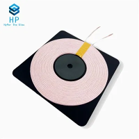
Now, let's talk about different types of Coil Inductors and their applications. There are various types of Coil Inductors, including air - core inductors, iron - core inductors, and ferrite - core inductors. Air - core inductors have low inductance values but are good for high - frequency applications because they don't have the losses associated with magnetic cores. Iron - core inductors can have high inductance values but are more suitable for low - frequency applications due to their higher core losses at high frequencies. Ferrite - core inductors are a popular choice for a wide range of frequencies as they offer a good balance between inductance and core losses.
Coil Inductors are used in a ton of different applications. One common use is in power supplies. In a switching power supply, Coil Inductors are used to store and release energy, helping to smooth out the output voltage and reduce ripple. They also play a crucial role in filter circuits. You can learn more about Filter Inductor which are a type of Coil Inductor designed specifically for filtering out unwanted frequencies.
Another important application is in power factor correction (PFC). PFC Inductor are used to improve the power factor of electrical equipment, which helps to reduce energy consumption and improve the efficiency of the power grid.
When it comes to designing with Coil Inductors, there are a few things to keep in mind. You need to consider the operating frequency of the circuit, the required inductance value, the current rating of the inductor, and the allowable core losses.
For high - frequency applications, you might want to choose an inductor with a low - loss core material and a design that minimizes parasitic capacitance. In low - frequency applications, you can focus more on getting the right inductance value and current handling capacity.
In terms of manufacturing Coil Inductors, it's a precise process. We start with the right type of wire, which can vary in terms of its gauge, insulation, and material. The wire is then wound around a core, which can be made of different materials depending on the application. The winding process needs to be carefully controlled to ensure the correct number of turns and the proper spacing between turns.
After the winding is done, the inductor might go through some additional processes like encapsulation or testing to make sure it meets the required specifications.
As a Coil Inductor supplier, I know that different customers have different needs. Whether you're working on a small - scale electronics project or a large - scale industrial application, we can provide a wide range of Coil Inductors to suit your requirements.
If you're in the market for Coil Inductors, Filter Inductors, or PFC Inductors, and you want to learn more about our products or discuss your specific needs, don't hesitate to reach out. We're here to help you find the perfect inductor solution for your project.
References:
- Halliday, D., Resnick, R., & Walker, J. (2014). Fundamentals of Physics. Wiley.
- Boylestad, R. L., & Nashelsky, L. (2011). Electronic Devices and Circuit Theory. Pearson.