




Accurately measuring the inductance of a PFC (Power Factor Correction) inductor is crucial for ensuring the optimal performance of power electronics systems. As a PFC inductor supplier, I understand the significance of precise inductance measurement in delivering high - quality products to our customers. In this blog, I will share some effective methods and considerations for accurately measuring the inductance of a PFC inductor.
Understanding PFC Inductors
Before delving into the measurement methods, it's important to have a basic understanding of PFC inductors. PFC inductors are key components in power factor correction circuits, which are designed to improve the power factor of electrical equipment. A high power factor reduces the reactive power in the system, leading to more efficient use of electrical energy and lower energy costs.
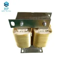
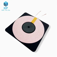
PFC inductors come in various shapes and sizes, including BUCK Inductor, Toroidal Inductors, and Coil Inductor. Each type has its own characteristics, but they all serve the same fundamental purpose of storing and releasing energy in the PFC circuit.
Factors Affecting Inductance Measurement
Several factors can affect the accuracy of inductance measurement. One of the primary factors is the frequency of the measurement signal. The inductance of a PFC inductor can vary with frequency due to the effects of parasitic capacitance and resistance. At high frequencies, the parasitic capacitance can cause the inductor to resonate, which can significantly affect the measured inductance.
Another factor is the DC bias current. In a PFC circuit, the inductor typically operates with a DC bias current. The inductance of the inductor can change with the magnitude of the DC bias current, especially in inductors with magnetic cores. This is because the magnetic properties of the core material can be affected by the DC magnetic field.
The temperature also plays a role in inductance measurement. The resistance of the inductor winding and the magnetic properties of the core material can change with temperature, which can lead to variations in the measured inductance.
Measurement Methods
1. Using an LCR Meter
An LCR meter is a commonly used instrument for measuring inductance. It works by applying a sinusoidal test signal to the inductor and measuring the voltage and current across it. The LCR meter then calculates the inductance based on the measured voltage, current, and the frequency of the test signal.
To measure the inductance of a PFC inductor using an LCR meter, follow these steps:
- Connect the inductor to the LCR meter according to the meter's instructions. Make sure the connections are secure to avoid measurement errors.
- Set the frequency of the test signal on the LCR meter. It's important to choose a frequency that is representative of the operating frequency of the PFC circuit. For example, if the PFC circuit operates at 100 kHz, set the test frequency of the LCR meter to 100 kHz.
- If the PFC inductor operates with a DC bias current, some LCR meters have a DC bias function. Set the appropriate DC bias current on the LCR meter and then measure the inductance.
- Take multiple measurements and calculate the average to improve the accuracy of the measurement.
2. Bridge Methods
Bridge methods, such as the Maxwell - Wien bridge and the Hay bridge, can also be used to measure inductance. These methods are based on the principle of comparing the unknown inductance with a known standard inductance or resistance.
The Maxwell - Wien bridge is suitable for measuring inductors with a relatively low Q factor (quality factor), while the Hay bridge is more appropriate for measuring inductors with a high Q factor.
The general procedure for using a bridge method is as follows:


- Set up the bridge circuit with the unknown PFC inductor, known resistors, and a standard inductor or capacitor.
- Adjust the variable components in the bridge circuit until the bridge is balanced. When the bridge is balanced, the voltage across the detector (usually a null detector) is zero.
- Calculate the inductance of the unknown PFC inductor based on the values of the known components and the balance conditions of the bridge.
3. Oscillator - Based Methods
Oscillator - based methods involve using an oscillator circuit with the PFC inductor as a part of the resonant circuit. The frequency of the oscillator is related to the inductance of the inductor.
By measuring the frequency of the oscillator and knowing the values of the other components in the oscillator circuit, the inductance of the PFC inductor can be calculated.
The steps for an oscillator - based measurement are:
- Build an oscillator circuit with the PFC inductor. The oscillator can be a simple LC oscillator or a more complex oscillator circuit.
- Measure the frequency of the oscillator using a frequency counter.
- Use the formula for the resonant frequency of the oscillator circuit to calculate the inductance of the PFC inductor.
Calibration and Verification
To ensure the accuracy of the inductance measurement, it's essential to calibrate the measurement instruments regularly. Calibration involves comparing the measurements of the instrument with a known standard.
After measuring the inductance of the PFC inductor, it's also a good practice to verify the measurement using an alternative method. For example, if you measured the inductance using an LCR meter, you can also use a bridge method to cross - check the result.
Conclusion
Accurately measuring the inductance of a PFC inductor is a complex but essential task. By understanding the factors that affect inductance measurement and using appropriate measurement methods, we can ensure that the PFC inductors we supply meet the required specifications.
As a PFC inductor supplier, we are committed to providing high - quality products. If you are interested in purchasing PFC inductors or have any questions about inductance measurement, please feel free to contact us for further discussion and procurement negotiation. We look forward to serving you and meeting your power electronics needs.
References
- "Handbook of Electrical Measurements" by John G. Webster
- "Power Electronics: Converters, Applications, and Design" by Ned Mohan, Tore M. Undeland, and William P. Robbins
- "Magnetic Components for Power Electronics: Theory and Design" by S. C. Wong and C. K. Tse